Hybrid bonding for chiplets: Unlocking BEOL-Level system integration

As AI pushes power and bandwidth limits, chiplets promise a new scaling path. Hybrid bonding goes beyond fine-pitch I/O, enabling BEOL-direct integration that reshapes system design across wafers and dies.
Fumihiro Inoue, Professor, YOKOHAMA National University
Why packaging now drives system-level scaling
AI demand accelerated by large language models is turning data-centre electricity consumption into a societal constraint. For decades, the semiconductor industry improved performance and energy efficiency mainly through scaling—shrinking devices and interconnects. Today, the rapid rise in AI compute demand is colliding with the practical limits of traditional scaling, forcing the industry to find new levers. Advanced packaging has therefore moved from “supporting technology” to a central driver of system progress.
Front-end-of-line innovation is not over. Nanosheet (gate-all-around, GAA) architectures, and longer-term concepts such as CFET that stack devices vertically, suggest that integration density per unit area can still increase. Yet the capital required is immense, and only a few companies can execute at scale. This reinforces industry consolidation and makes supply capacity and lead time more dependent on a small number of players. At the same time, higher process complexity translates into yield pressure. As scaling slows, integration often pushes die sizes larger, reducing dies per wafer and amplifying the yield penalty. Moreover, next-generation integration approaches—such as CFET and backside power delivery network (BSPDN)—carry strong design and thermal constraints, making it harder to assume that energy efficiency will improve “automatically” with each node as it often did in the past.

Figure.1 Chiplet integration is inherently layered across the stack
In this environment, chiplet architectures enabled by advanced packaging are gaining momentum. The core idea is to partition functions once integrated into a monolithic SoC and then re-integrate them in an optimized way. By manufacturing functional blocks—xPU, SRAM, SerDes, modems—separately, each die can be smaller, and yield can improve. Different nodes can be selected per function, enabling IP reuse and cost optimization.
For AI systems, the most powerful benefit is often interconnect redesign. In GPU–HBM configurations, latency, bandwidth, and interconnect power strongly shape system performance. Chiplets allow the interconnect structure itself to be rebuilt—for example, by embedding fine-pitch bridge dies only where ultra-dense interconnect is required. This is why chiplets have become a leading path for “scaling beyond lithography” in the AI era.
Chiplets are a stack of layers, not a single technology
Chiplets are often introduced as a concept and a design philosophy. In practice, the technical landscape is broader and more layered than it appears. The term “chiplet” now spans device vendors, foundries, OSATs, and substrate manufacturers. Many groups develop under the same banner, even though they operate at different layers and historically produced different product categories. As a result, technologies that used to be distributed across distinct layers can appear to blur under a single label, which can hinder clear discussion.
Interposers and substrates, for example, are frequently treated as separate categories, yet they share many development items: RDL formation, microbump fabrication, warpage reduction, and more. When discussing chiplets, it is therefore essential to clarify which layer is being addressed and how a given development activity fits into the overall integration stack.
Chiplet integration also faces several manufacturing bottlenecks. A prominent one is chip-to-chip I/O density. Solder-based microbumps remain widely used, but their practical pitch often sits around several tens of micrometres. Thermo-compression bonding relies on simultaneous heating and pressing, which increases short-circuit risk at finer pitches and raises concerns around resistance and thermal performance. Economics add another layer of difficulty: chiplets are often motivated by cost and yield optimisation, yet advanced packaging can become expensive, demanding careful optimisation across design, process, equipment, and yield. Thermal management and test—especially in relation to Known Good Die (KGD) and system-level inspection—remain tightly coupled to architecture choices.
Among these many challenges, this feature focuses on hybrid bonding as a key technology to move beyond the limitations of microbumps in chip-to-chip interconnect.
What hybrid bonding really changes
Hybrid bonding is frequently described as the next step after microbumps. In reality, its value extends beyond fine-pitch I/O replacement. Its deeper potential lies in design freedom: hybrid bonding can make chiplet partitioning and re-integration practical at the BEOL level.

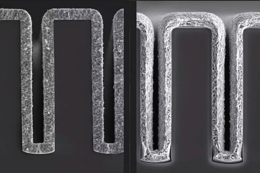
Figure.2 Why hybrid bonding goes beyond microbumps. Compared with solder microbumps, hybrid bonding enables finer pitch and BEOL-like connectivity across die boundaries, turning chiplet integration into an architectural design tool
Technically, hybrid bonding is rooted in the same foundation as damascene copper interconnect formation. It bonds wafers (or dies) without an adhesive layer and without solder bumps. Planarized dielectric surfaces come into contact and mechanically bond, while facing copper pads are simultaneously aligned. Subsequent thermal treatment promotes copper self-diffusion and forms robust Cu–Cu bonds. In short, dielectric bonding and metal interconnect bonding are achieved in a single bonding operation—hence “hybrid”.
Architecturally, hybrid bonding is compelling because it can be approached with a BEOL-like mindset. If the interface were simply an I/O connection, it might be treated as a separate design domain, as microbumps often are. Hybrid bonding, however, can span BEOL hierarchies across the die boundary. It effectively allows interconnect optimization and architectural thinking once confined within a monolithic SoC to be “exported” beyond the die boundary. Signals can be moved vertically across chips over the shortest physical distance, turning chiplet integration into an architectural tool. This aligns with the “CMOS 2.0” framing often used to describe a new era of system scaling.
Wafer-level hybrid bonding has already progressed from development into high-volume applications. CMOS image sensors [1] were an early driver, and adoption has expanded beyond that domain. In NAND, for example, the CMOS circuit wafer and the memory array wafer can be manufactured separately and then integrated via hybrid bonding in a CMOS Bonded to Array (CBA) scheme [2]. In such applications, bonding has reached regimes below 1 µm pitch, well beyond what is practical with microbumps.
Scaling barriers: CMP, metrology, overlay, reliability and test
Scaling hybrid bonding into robust and economical manufacturing is a “total engineering” challenge spanning tightly coupled layers. Key issues can be grouped into: (1) surface preparation, (2) surface evaluation and characterization, (3) physical/chemical mechanism control, (4) overlay (alignment) error and root-cause analysis, (5) interconnect reliability, and (6) testability and inspection flow.
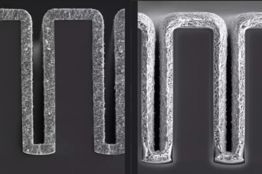
The most critical step is often CMP and associated upstream/downstream processes that bring copper and dielectric into a highly planar state. In hybrid bonding, subtle topography variation or copper recess non-uniformity can drive voids, non-bonded regions, and electrical failure. Control must extend across wafer- and die-scale flatness, edge roll-off, dielectric roughness, and copper pad erosion and recess—far tighter than typical BEOL CMP requirements.
Metrology can become a bottleneck. AFM provides high-precision local information but is limited in the throughput and sampling area. This motivates broader-area, higher-throughput optical metrology and inline inspection, as well as process schemes that manage interface state from cleaning/activation to bonding, including sensitivity to queue time.
Mechanism understanding is also evolving. Increasing attention is being paid to the coupling between bonding mechanics (bond-front or bond-wave propagation) and surface chemistry. Bond-front stability can influence defect formation, including particle-driven voids and local non-bonded regions. As a result, “how bonding progresses” is increasingly treated as an engineering variable rather than an uncontrollable outcome [3].
Overlay requirements tighten sharply as pitch moves into the sub-micron range. Following the initial contact (often triggered near the wafer centre), a bond wave propagates rapidly—on the order of 10 seconds across the wafer—typically as concentric fronts. Meanwhile, maintaining <25 nm misalignment across the full wafer becomes necessary, a far more stringent requirement than conventional scanner lithography [4]. Because the interface effectively “locks” upon contact, the overall placement–metrology–correction loop ultimately determines success.
Reliability evaluation is advancing both mechanical integrity (interfacial strength and fracture modes) and electrical stability (contact resistance variation and degradation under thermal/stress conditions). Meanwhile, hybrid bonding introduces test constraints: because planarity is critical, direct probing copper pads using conventional probe cards can be difficult, and pad choices may be restricted. Test strategy, therefore, needs to be integrated into development rather than treated as an afterthought.
Die-Level hybrid bonding: The hard part of chiplets
Wafer-level hybrid bonding will likely expand and continue scaling in pitch and yield. In parallel, chiplet growth depends on extending hybrid bonding to die-level integration. Many products require selective assembly and KGD usage, which pushes integration towards die-to-wafer (D2W) hybrid bonding.

Figure.3 Wafer-level vs die-level hybrid bonding: the process reality. Die-level flows add thinning/singulation, surface handling, residue/particle risks, activation-to-bond time lag, and stricter overlay control—often with limited opportunity for self-alignment once contact occurs
A widely recognized early example is AMD’s 3D V-Cache, where a cache die is hybrid-bonded onto a logic die using foundry-level 3D integration capability. Yet adoption remains limited, and broader application still faces significant hurdles.
Die-level hybrid bonding must overcome almost all wafer-level challenges—surface preparation, characterization, mechanism control, overlay, reliability—while also addressing die-specific problems. A representative example is thinning and singulation. Wafer-level flows can often thin and dice after bonding; die-level flows typically thin and singulate first. If the hybrid-bonding surface is formed upfront, it must survive interactions with temporary bonding materials or backgrinding tape, and singulation. Residues, contamination, and micro-particles that are less critical at wafer level can become direct yield killers at die level.
Singulation therefore requires careful engineering. Plasma dicing can reduce residues and particles, but cost and equipment constraints matter. Blade dicing continues to improve as well, with approaches aimed at minimizing particle generation. Beyond singulation, die bonding tools are under active development, including handling and transport schemes that minimize or avoid contact with sensitive surfaces—approaching non-contact pick-and-place [5].
Another die-level bottleneck is the activation-to-bond time lag. In wafer-to-wafer flows, this interval can often be kept short because both wafers are processed and bonded in close succession, for example within a wafer-to-wafer cluster bonder. By contrast, sequential die-level assembly involves repeated transport, alignment, and bonding steps, resulting in longer and more variable queue times for each die. Surface deactivation during these delays can reduce bond strength and ultimately impact yield. Moreover, standardized methods to quantify these effects—particularly robust bond-strength metrology—are not yet fully established, which further slows development.
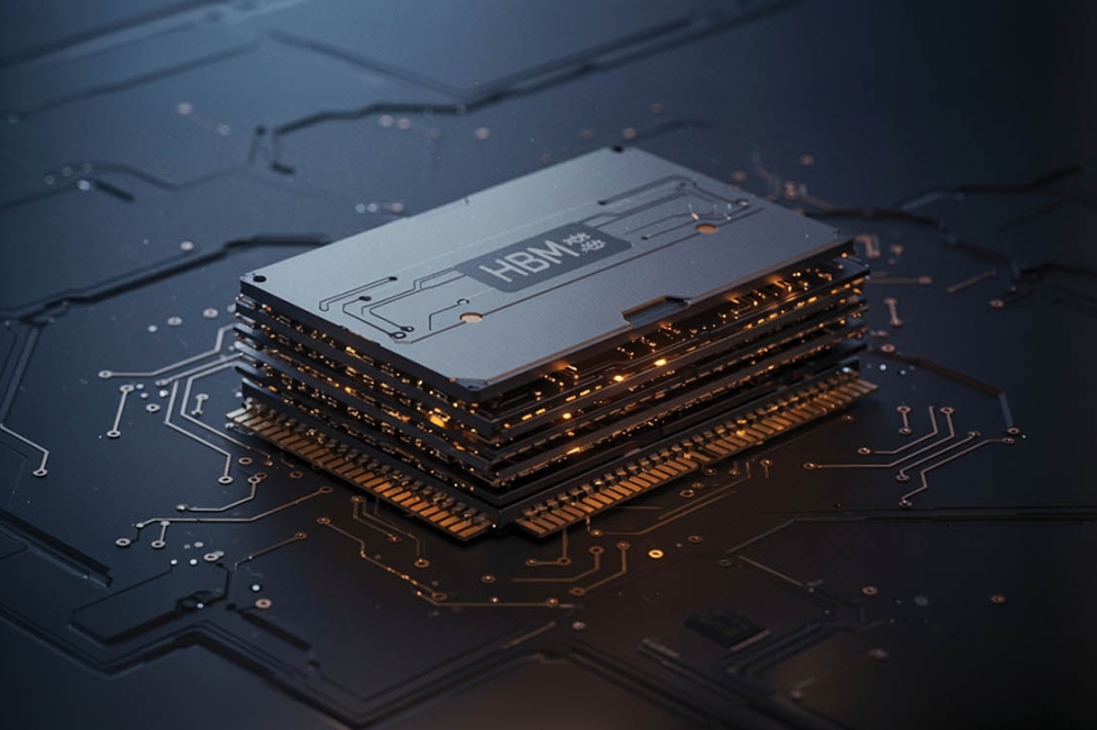
Hybrid bonding is also discussed as a potential future enabler for high-bandwidth memory stacking. Yet achieving very high yields across extremely tall stacks (for example, ~18–20-high) and managing demanding configurations such as face-to-back hybrid bonding with Through-Si vias (TSV), remain a major challenge.
Outlook: From cloud AI to edge/physical AI
Hybrid bonding changes more than metrics such as resistance, interface thickness, thermal pathways, and pitch. Once BEOL-direct bonding becomes practical, it reshapes the boundary between interconnects and architecture and has the potential to update design philosophy itself. When aligned with the chiplet concept, hybrid bonding becomes not merely a bonding technique but a starting point for new integration structures—a bridge between front-end and back-end technologies that is likely to become indispensable for future 3D integration.
Significant barriers remain, especially for die-level hybrid bonding. Process-driven variability—introduced by thinning, singulation, handling, residue control, and activation-to-bond time lag—can severely impact yield. A promising strategy is to migrate the hardest aspects of die-level assembly into wafer-like workflows. One such direction is reconstructed die-to-wafer (D2W) hybrid bonding, which reconstitutes multiple dies on a carrier into a unified “pseudo-wafer”. This allows subsequent planarization, interconnect, and bonding to leverage wafer-level process maturity while reducing reliance on individual die handling. Intel has described a closely related concept under the term quasi-monolithic chips (QMC)[6]. Gap fill, planarization control, and placement-error propagation remain key challenges, but the direction is clear: wafer-like reconstitution may open new paths for chiplet-scale integration.
This direction is particularly compelling for edge and physical-AI systems, where constraints on form factor, power, heat dissipation, and long-term reliability are often tighter than in cloud deployments. By enabling finer-pitch, shorter interconnects and tighter co-integration without resorting to large interposers or oversized substrates, wafer-like reconstitution can help reduce interconnect energy, improve thermal paths, and support compact, robust modules suited to harsh operating environments and extended lifetimes.
Hybrid bonding will not be a sprint; it is a medium- to long-term competition spanning process, metrology, design, and test. The prize, however, is substantial: chiplets not merely as a cost optimization tool, but as a platform that liberates system-level design freedom.